Wpf Cube Three Dee
My Cube (3D graphics in Wpf)
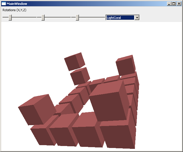
At the end of this little tutorial you should be able to create an application that produces a number of cubes and lets the user rotate and zoom (rotate with sliders and zoom with mouse wheel). It will look a little something like the below screen shot. If you are very impatient you can scroll to the bottom of this page and download the source code.
Lights, Camera... Action!
3D-graphics in WPF is remarkably simple to set up - you just add a camera, some light and then some objects. In the tutorial from Wpf Tutorial (see [1]) a very simple example is shown with the following principle XAML:
    <Viewport3D>
        <Viewport3D.Camera>
            <PerspectiveCamera ... />
        </Viewport3D.Camera>
        <ModelVisual3D>
            <ModelVisual3D.Content>
                <Model3DGroup>
                    <DirectionalLight ... />
                    <GeometryModel3D>
                        ...
                    </GeometryModel3D>
                </Model3DGroup>
            </ModelVisual3D.Content>
        </ModelVisual3D>
    </Viewport3D>
As you can see in the XAML code above there is a Viewport3D with a camera and a model. The model has some light and a geometry model. This idea will follow in my little example. But I am building the model in a programmatic way instead of declaring everything in XAML.
The Triangles
The base of all 3D-graphics is the triangle. I will not explain much of the details (again see the tutorial at Wpf Tutorial or see the other links below) - I will instead try to explain the code behind how I make triangles in this example.
The code is borrowed from [2] and uses a helper-method to help build the triangles (this will later be used to build the cubes). As you can see in the code snippet below this helper creates a Model3DGroup - this is used in the WPF snippet in the above section. So here we are using code to generate the triangles, this is to me a lot more sensible since we can easily reproduce this many times. As you can see we are also adding a material using a brush.
    public Model3DGroup CreateTriangle(Point3D p0, Point3D p1, Point3D p2)
    {
        MeshGeometry3D mesh = new MeshGeometry3D();
        mesh.Positions.Add(p0);
        mesh.Positions.Add(p1);
        mesh.Positions.Add(p2);
        mesh.TriangleIndices.Add(0);
        mesh.TriangleIndices.Add(1);
        mesh.TriangleIndices.Add(2);

        Vector3D normal = VectorHelper.CalcNormal(p0, p1, p2);
        mesh.Normals.Add(normal);
        mesh.Normals.Add(normal);
        mesh.Normals.Add(normal);

        Material material = new DiffuseMaterial(new SolidColorBrush(_color));
        GeometryModel3D model = new GeometryModel3D(mesh, material);
        Model3DGroup group = new Model3DGroup();
        group.Children.Add(model);
        return group;
    }
The Cube
I want to be able to add a lot of cubes to my Viewport3D so I have a method (again I started off with code from Codegod) that generates a cube in the point (x, y, z). In short this method creates 8 points (the corners of the cube), 12 triangles (two for each side of the cube) and adds this to a 3D model (a Model3DGroup).
    public ModelVisual3D Create(int x, int y, int z)
    {
        Model3DGroup cube = new Model3DGroup();

        int A = 5;
        int B = 5;
        int C = 5;

        Point3D p0 = new Point3D(0 + x, 0 + y, 0 + z);
        Point3D p1 = new Point3D(A + x, 0 + y, 0 + z);
        Point3D p2 = new Point3D(A + x, 0 + y, C + z);
        Point3D p3 = new Point3D(0 + x, 0 + y, C + z);
        Point3D p4 = new Point3D(0 + x, B + y, 0 + z);
        Point3D p5 = new Point3D(A + x, B + y, 0 + z);
        Point3D p6 = new Point3D(A + x, B + y, C + z);
        Point3D p7 = new Point3D(0 + x, B + y, C + z);

        //front
        cube.Children.Add(CreateTriangle(p3, p2, p6));
        cube.Children.Add(CreateTriangle(p3, p6, p7));

        //right
        cube.Children.Add(CreateTriangle(p2, p1, p5));
        cube.Children.Add(CreateTriangle(p2, p5, p6));

        //back
        cube.Children.Add(CreateTriangle(p1, p0, p4));
        cube.Children.Add(CreateTriangle(p1, p4, p5));

        //left
        cube.Children.Add(CreateTriangle(p0, p3, p7));
        cube.Children.Add(CreateTriangle(p0, p7, p4));

        //top
        cube.Children.Add(CreateTriangle(p7, p6, p5));
        cube.Children.Add(CreateTriangle(p7, p5, p4));

        //bottom
        cube.Children.Add(CreateTriangle(p2, p3, p0));
        cube.Children.Add(CreateTriangle(p2, p0, p1));

        ModelVisual3D model = new ModelVisual3D();
        model.Content = cube;
        return model;
    }
The Cubes
As you could see in the code that generates a cube the side was hard-coded to 5. This is of course not very elegant - but as a first example I think it is ok. In the code below, where I make a lot of cubes I place them in a grid of size 6 - so that there will be a 20% space between each cube. I place them in a "castle" like layout.
    public void Render()
    {
        CubeBuilder cubeBuilder = new CubeBuilder(CubeColor);

        int A = 6;
        int B = 6;
        int C = 6;

        // origin
        mainViewport.Children.Add(cubeBuilder.Create(0, 0, 0));

        //side 1
        mainViewport.Children.Add(cubeBuilder.Create(1 * A, 0, 0));
        mainViewport.Children.Add(cubeBuilder.Create(2 * A, 0, 0));
        mainViewport.Children.Add(cubeBuilder.Create(3 * A, 0, 0));
        mainViewport.Children.Add(cubeBuilder.Create(4 * A, 0, 0));

        //side 2
        mainViewport.Children.Add(cubeBuilder.Create(4 * A, 1 * B, 0));
        mainViewport.Children.Add(cubeBuilder.Create(4 * A, 2 * B, 0));

        //side 3
        mainViewport.Children.Add(cubeBuilder.Create(4 * A, 3 * B, 0));
        mainViewport.Children.Add(cubeBuilder.Create(3 * A, 3 * B, 0));
        mainViewport.Children.Add(cubeBuilder.Create(2 * A, 3 * B, 0));
        mainViewport.Children.Add(cubeBuilder.Create(1 * A, 3 * B, 0));
        mainViewport.Children.Add(cubeBuilder.Create(0 * A, 3 * B, 0));

        //side 4
        mainViewport.Children.Add(cubeBuilder.Create(0, 2 * B, 0));
        mainViewport.Children.Add(cubeBuilder.Create(0, 1 * B, 0));

        //corner 1
        mainViewport.Children.Add(cubeBuilder.Create(0, 0, 1 * C));
        mainViewport.Children.Add(cubeBuilder.Create(0, 0, 2 * C));

        //other corners
        mainViewport.Children.Add(cubeBuilder.Create(4 * A, 0 * B, C));
        mainViewport.Children.Add(cubeBuilder.Create(0 * A, 3 * B, C));
        mainViewport.Children.Add(cubeBuilder.Create(4 * A, 3 * B, C));
    }
Rotating and Zooming
Rotation
In order to rotate what we see we are adding a rotation transform on the camera (an into to transforms can be found at MSDN: [3]). In my example we insert this transform in the XAML code of the camera:
    <Viewport3D.Camera>
        <PerspectiveCamera ... >
            <PerspectiveCamera.Transform>
                <Transform3DGroup>
                    <RotateTransform3D>
                        <RotateTransform3D.Rotation>
                            <AxisAngleRotation3D x:Name="rotX" Axis="1 0 0" Angle="0" />
                        </RotateTransform3D.Rotation>
                    </RotateTransform3D>
                < ... >
            < ... >
        < ... >
    < ... >
This rotation is modified using a slider that we introduce in the XAML code:
    <Slider Name="rotateX"
        Minimum="0" Maximum="360"
        Value="0" Width="120"
        ValueChanged="rotateX_ValueChanged" />
The slider raises an event once modified that in turns call a rotate method. In that method we are modifying the angle of the rotation-transform:
    private void rotateX_ValueChanged(object sender, RoutedPropertyChangedEventArgs<double> e)
    {
        RotateX(e.NewValue);
    }

    public void RotateX(double angle)
    {
        rotX.Angle = angle;
    }
The zoom
The zoom functionality was heavily inspired by the examples at this excellent Code Project article: [4] .
We want the mouse wheel event on the window and not just the Viewport3D to trigger a zoom code. we first add the event to the window block of the XAML code.
<Window ... MouseWheel="Window_MouseWheel">
In the code we update the position (z only to simplify things) by this simple code block. In principle we reposition the camera.
    private void Window_MouseWheel(object sender, MouseWheelEventArgs e)
    {
        mCamera.Position = new System.Windows.Media.Media3D.Point3D(
            mCamera.Position.X,
            mCamera.Position.Y,
            mCamera.Position.Z - e.Delta / 250D);
    }
Download Visual Studio Solution
You can download the Visual Studio solution file (here [5]) and play around with it.
Acknowledgments
- A starting point at Wpf Tutorial: [6]
- Mouse wheel event and depth from the Code Project: [7]
- Major inspiration and a lot of code came from Codegod: [8]
This page belongs in Kategori Programmering